Thursday 3 October 2024

435 Centreboard Cylinder Removal

435 Centreboard Cylinder Removal

The following is based on my experience with my 2001 OVNI 435 #6.  It may not reflect any changes to the 435 through the years.   Any input to improve this document is welcome.  

Specific tools required 

  • Flare (helpful) and 14mm open ended wrenches
  • Hammer and drift for 10mm pins
  • small 90 degree pry bar to assist with removing covers.  
The centreboard cylinder is situated within the centreboard trunk, positioned horzontally above the  centreboard.   It is not necessary to remove the centreboard to remove the cylinder as there are access covers on top of the trunk for this purpose.   
In order to remove the centreboard cylinder, you will need to first gain access to, then remove the two pins that secure the cylinder.  The forward pin fastens the cylinder's piston rod to the centreboard.   It is the extension and retraction of the piston rod that raises and lowers the centreboard.   The aft pin anchors the cylinder base between reinforced areas on the opposite sides of the centreboard trunk.  Once both pins are removed, and you can disconnect the 2 hydraulic hoses and lift the cylinder through the access cover. 

In preparation, the centreboard must be safely supported in the fully-retracted position. Lower the board slightly to ensure the cylinder is no longer bearing the board's weight, and can be safely removed. 

Gaining Access

To access the hoses, first remove the plywood cover opposite the galley fridge.  This cover fills the triangle between the main bulkhead and the settee corner.   You will see the hoses and the acrylic  cover though which they pass into the trunk, via cable glands.  (which may have become brittle and broken with age)    
  1. Remove the cable ties securing the cables to the bulkhead.   
  2. Note the fore/aft orientation of the acrylic cover.
  3.  Slack off the gland nuts and remove the cover screws.  
  4. Gently pry the cover free and slide it up the cables.   It is through this opening that the cylinder will be withdrawn.  
The 10mm forward pin is accessed from the top and sides of the centreboard trunk in the forward cabin.
  1. Remove the plywood trim covers from the top and starboard side of the CB trunk and lift the plywood berth board to gain access to the two upper aluminum covers on either side of the trunk, and the acrylic cover on top.  
  2. The aluminmum covers are secured by M4 philips screws, and sealed with Sikaflex.  You will likely need to use a small pry bar to break the cover free of the sealant.   
  3. With the covers removed, you will see the cylinder's piston rod end where it engages the CB via the 10mm pin, itself secured with two cotter pins.  If you do not have complete access to this, the board is not fully retracted.  
The 10mm aft pin is accessed by removing  two small aluminum covers located on either side of the centreboard trunk, roughly opposite the fridge.  The starboard side cover is concealed beneath a plywood trim panel, the portside cover is under the  forward end of the settee, most easily accessed by unscrewing the removing the plywood panel that forms the seat.  
  1. Remove the plywood trim cover and unscrew and remove the plywood panel that forms the forward dinette seat. 
  2. Remove the square aluminum covers. The 10mm pin will be seen seated in its close-fitting hole.  
Once all the covers are removed clean the area as much as possible. Remove any residual sealant.

Removing the Cylinder

Removing the forward pin first allows the piston rod to be fully retracted which is necessary for removal, but also eases the next steps and ensures that the more difficult-to-remove aft pin is not binding in the cylinder. 

  1. The forward pin is secured by cotter pins. Remove one or both of the cotter pins and drift the pin out.   
  2. The pin should yield to moderate taps with the hammer and punch.  If not, first use the hydraulic pump to ensure that the cylinder is not still loaded with the weight of the centreboard.  If badly corroded or bent it may be difficult to remove.   
  3. Once the forwad pin us removed, using the hydraulic pump, select the position used to lower the board, and pump to fully retract the cylinder's piston rod.  
  4. Carefully drift the aft pin out with a hammer and drift, from starboard to port.  This pin may be extremely difficult to remove due to corrosion, the amount of contact area, and the pin's the close fit in its holes.   Once this second pin is removed the cylinder will be lying loosely on top of the centreboard, connected only by the hoses. 
  5. Disconnect the hoses using an open-end 14mm wrench for the nut and a second flare wrench to prevent the hose from turning while doing so.   Some fluid will be released as the fittings are loosened.   
  6. When both hoses are disconected, tape the ends to prevent any debris from entering the system.
The cylinder can now be removed.

Reassembly

(If you are reading this you already know about sealants, and where and how Tefgel/Lanolin must be generously applied.)

Reassembly is generally the reverse of the above, with a few additonal hints.   
  1. Before proceeding, ensure that the piston rod is fully retracted and that the holes in the cylinder base and the piston rod are in the same plane, by rotating the rod as required.  It'll probably be stiffer than you expect, and may require some leverage.  
  2. Place the cylinder in the trunk in the correct orientation.   (base aft, fittings up)   
  3. Switch the hydraulic pump to the "raise" position, and cycle it until it spurts fluid from the aft hose.  This helps ensure the hose is free of debris and excess air.    
  4. Connect the aft hose only.   
  5. Insert the rear pin to secure the cylinder base to the CB trunk.    
  6. Use the hydraulic pump (still in the "raise" position) to slowly extend the piston rod.  Guide the rod end between the centreboard flanges and pin it in place.   Do this slowly and be careful not to overextend the cylinder.  (You will need two people to do this efficiently.)
  7. Celebrate the fact that you've mostly purged the cylinder of air.
  8. Switch the pump to the "lower" position, and as before cycle the pump to purge the forward hose. 
  9. Reconnect the hose, and switch the pump back to the centre "locked" position.
  10. The system will now be operational but must be fully purged of air.   
  11. Once you are certain the system is functioning and connections are leak-free, replace and seal the aluminum covers and acrylic covers.  Do not reinstall the trim, tighten the glands or secure the cable ties.
  12. After the boat is launched, fully cycle the hydraulic system.   With the board down, secure the hoses with new zip ties and tighten the cable glands.
  13. After ensuring that there are no seawater leaks, replace the trim and cosmetic covers.

Misc photos and notes

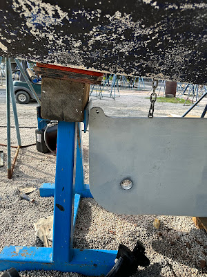
The photos below show the flanges on the centreboard, between which the cylinder's piston rod is pinned.  If you are replacing the cylinder, ensure you order the correct part as it changed during the 435's production run.   

The photo below shows the two configurations of cylinder ram.   Note the different length of the flat section.   


The photo below shows the aft pin, and how it engages the cylinder base and the reinforced sides of the centreboard trunk   Note that I cut this access hole myself in order to saw off the pin as it could not be removed otherwise.   
The photo also shows the two nuts used to secure the hose to the 90 deg. male fitting on the cylinder.  The upper (in the photo) nut is held firm while the nut adjacent to the fitting is turned.


Wednesday 2 October 2024

Battery Installation Details

Upgrading The Battery Bank


The 435 Battery box  measures 22.5" X 30.25"X 9.5" deep and is located below the cockpit.  It is made of welded aluminum and is bolted in place. It has an outward turning 2" flange around the top, with a seperate, single-piece plywood lid,     With the lid removed, the batteries are partially accessible from either aft cabin.  The electrical connections are made on the port side.    

The one-piece plywood cover is secured to the flange with machine screws and easily-dropped nuts, and it has a 2"X2"  (approx) cleat around its perimeter.   It is bulky and inconvenient in use, and access is more difficult than it needs to be. In this case Alubat did the minimum required to meet only the most basic requirement.  Thankfully it can easily be improved.

Cables enter the battery compartment through randomly-drilled holes on the port side.   There is no positive bus bar, and no fusing at the batteries,    Over time, accessories with a mishmash of fuse styles (or none) have been stacked on the various battery terminals. none labelled, most with no means of disconnect.  The cables intrude into the box, interfering with battery installation and removal.   

The house bank's 4 group 31 batteries were connected in parallel with heavy, well-made jumper links.  With the limited clearance to the conductive cockpit sole above, caution is required when working here, especially with top-terminal batteries.  

The starter battery was/is also in this box, furthest aft.  Access is particularly inconvenient.   

The photos below show:

  • how access is restricted by the cockpit, 
  • how the cabling was installed and intrudes into the box.
  • The many live connections that must be made in an awkward, confined space.    

Below left you can see that batteries must be placed in the box or removed from it in a fore and aft orientation.  Below right shows a pair of terminals in the cockpit locker that were connected to the starter battery.    Presumably this was to provide for boosting or charging.  This DIY hack has been removed, and I will eventually relocate the starter battery to a more accessible location, probably in the port side cockpit locker. 


What to do?

  With the upgrade from 4 group 31 to 2 group 4d (ish) lithium batteries, it became a necessary to re-think the stowage of the batteries, and opportune to upgrade the installation with a bus bar, circuit protection, and a safer, more orderly layout.  There's plenty of opportunity for improvement.

Scope

  1. determine battery orientation  ensuring:
    1. optimal use of space, 
    2. minimal wiring
    3. tool-less method to install/secure/remove batteries. (small ratchet straps?)
    4. must be easy to reconfigure with - at most - basic woodworking tools.    
    5. Battteries must be well secured
    6. Ideally, either house or start betteries could be removed while leaving the others in place.
  2. design/install distribution and circuit protection for current uses and future expansion
    1. Likely this means locating the bus bar and fusing outside of and adjacent to the battery box for better access, however it must then be protected from accidental contact.    
    2. it should be easy and safe to disconnect each battery while leaving the other(s) in use.
    3. a ATO/ATC "blade" fuse block may be required for some low-current accessory connections.   
  3. Improve the cover
    1. Cut the existing cover in a fore and aft direction. 
    2. Incorporate a tool-less means of securing the cover so that either side can be quickly accessed. 
    3. Ensure that terminal fuses can be inspected and replaced from the port side.   
  4. Incorporate storage into any unused space if possible.
  5. Insulate the interior sides of the battery box to reduce the risk of contact with a live conductor.
  6. Provide clearly marked storage for spare fuses nearby.

The Physical part - Thinking inside the box.

Due to the size and shape of the batteries and the restricted access to the box, satisfying the above critieria is trickier than it first appears.  Particularly item 1.6, as the batteries must be placed in the box in a fore-and aft orientation  and then rotated atwhartships if that is the intent.  This creates a bit of an assembly puzzle.   I decided to create a mdf mock up of the box and batteries in the shop to experiment with different approaches.  

I ultimately decided to arrange the batteries as pictured, with a hold down system comprising several oak rails.   I firmly bolted two 2" wide rails 2" above the bottom, at either end of the box.  In the photo these can be seen at each end of the narrow ends of the box. Note that the postive terminals are at what will be the forward end of the box.   The 2" space around the perimeter creates a protected space for the cables and potentially terminal fuses. 

30" long, 2"X2"  movable rails, running the length of the box, are placed in the empty box,  under the raised. fixed rails, which then prevent them from lifting.  The batteries are placed between these.  A ratchet strap can be looped around these movable rails to secure the house batteries.   Wooden blocks can be used in the remaining space to further secure movable rails (and therefore the batteries) laterally.  No tools required.

Parts of Oak

The mdf protoype worked well, so a more refined version was committed to red oak.  Will post pics when the varnish dries.   You can see the short end rails with the M8 bolt holes, and the movable rails with the added refinement of a cleat to secure the hold down strap.  


The Electrical Part - Safe and Simple?

Circuit Protection at Battery box


Based on the info above and the cabling already in place, the following circuit protection should be incorporated. 
  1. Battery 1 terminal fuses @150a
  2. Battery 2 terminal fuses @150a
  3. Inverter charger 1600w/70a (100A)
  4. Small inverter.  (40A)
  5. 70A Alternator via smart regulator (verify cable, regulator output)
  6. House loads (125A per dwg, s/b fused already - where?)
  7. Future water maker (100A circuit?)
  8. 200W (450W future) PV (50a)
  9. 200W Sailgen (50a) 
  10. Wind (50a)  **  The wind generator may be retired.
That’s a lot….  Too much in fact.   It will be consolidated.

Bus bars, circuit protection and monitoring

After having purchased the necessary bus bars and breakers to upgrade the DC distribution, I struggled to design a safe and compact electrical layout that would work in the limited space available.  This brought me back to Victon, and their Lynx range.   I had previously ruled this out as being much too expensive, but...   it isn't.     While the lynx shunt wasn't absolutely necessary it provided the opportunity to further consolidate components.   The Lynx Power-In has been "hacked" to incorporate fuses.  (google it) 
The larger fuses and breakers are of a type and rating to protect in the event of a dead short.   This is a topic worth investigating.    So, I wet about building a sub assembly on a piece of scrap polycarbonate that could be fastened to the side of the battery box.   
This too tok some thought.  

 Below you can see the space around the perimeter of the batteries and the oval holes at either end for the battery cables.     The pairs of battery cables will fasten the bus bars (red and black covers in the photo.)  There is very little cable exposed.  
There are fuses on each battery terminal and a very fast fuse in the lynx shunt.  
All other cabling will enter at the bottom of the Lynx power in, where it connects to a fuse and the bus bar.  The shunt is correctly located between all grounds and the battery Hopefully I can simplify and remove some of the massive amount of cabling and trunking that runs beside the battery box!  


Notes

Fuses required 

CNN350DIN.   Fast fuse for dead short, in lynx shunt.

Mbrf for terminal fuse disconnect battery.  There is a problem here in that either end of the wire will remain live.  For disconnect it should be at the lynx shunt.  
Mega (50.8mm) fuses within the lynx shunt.  
Littelfuse makes mega/AMG fuses as low as 40a


435 Centreboard Cylinder Removal

435 Centreboard Cylinder Removal The following is based on my experience with my 2001 OVNI 435 #6.  It may not reflect any changes to the 43...

Posts by Subject