FleetOne antenna relocation & new composite antenna mount.
As already stated, Sakura was equipped wth a Cobham sailor FleetOne satellite telephone and Redbox router. I had been advised that this system was out of date and decided to replace it with the cheaper, faster and more popular Starlink. I have since reconsidered this and will retain the Inmarsat system, and use it for emergencies, weather, and minimal messaging.
Revising the Antenna mount.
The FleetOne antenna is fairly compact and at 2.6kg is not terribly heavy. After some thought, I decided to mount it on a platform bolted to the arch and extending forward far enough for the antenna to clear the solar panels. (The stern light is at the rear and must remain unobstructed) While at the boat I templated the curve on the top of the arch so I could construct a fitted composite bracket at home.
There were a few things to consider in designing the mount:
- it must be compact, lightweight, and adequately stiff and fatigue-resistant as the antenna is a mass perched at the end of a lever that subject to constant cycling..
- The antenna mounting area is flat while the other end must conform to the curve of the arch, where it will be secured with the 4XM8 through-bolts that had previously secured the wind generator's mounting post.
- The solar panels reside above where the bracket will mount, so the bracket must be low-profile enough fit beneath them.
- There should be access to the wiring opening on the top of the arch, which will be covered by the bracket, otherwise future access will be quite inconvenient. This may not matter much in practice. I will prepare by making a curved panel that can be secured as a cover.
- The installation should be simple, require zero maintenance and not look like a DIY effort.
With all that in mind, I decided to use two layers of a honeycomb core material called Nidacore, sandwiched between mulitple layers of biaxial stitch-mat, laminated with epoxy resin. (Nidacore is not ideal for this, but I had some on hand) Construction is kinda' like one of those hazelnut wafer cookies that shouldn't be good, but is.
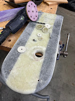
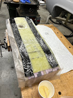
After making a form from some scrap, the various alternating layers were progressively laminated. The Nidacore layers were beveled at one end to conform to where they landed against the transition to the curved section, and this bevelled area was bedded/bonded with very thick glass-filled epoxy putty for strength and to ensure no voids. . (This is the where the stresses from the constant flexing will concentate). The 'glass was tripled across that area as well, but otherwise runs end-to end for strength, including a lamination between the two layers of Nidacore, The exposed edges were filled with dense glass-filled epoxy putty which was smoothed and radiused, then glassed over twice by wrapping the edes of a final bottom layer of stitch mat up, and then this overlapped with the top layer down around the entire perimeter. .In the photos you can see some carbon fibre tape laid into both sides beneath those final layers of stitch mat. No reason for this other than I had some on hand, as one does, but it likely adds to the stiffness. (and will make the boat go faster) Before the final laminations were done, the antenna mounting holes were laid out and bored oversized, then filled with putty and pilot drilled. Finally, reinforcing discs were fastened where the mouting bolts bear. It will require some trimming to fit and will therefore be painted on site. I will use 3m 4200 to bed/adhere it to the arch for extra security and to prevent it from shifting/wandering.


No comments:
Post a Comment