The rudder blade was disassembled and its hardware was replaced in 2023
The screws securing the cover are FHMS M5 .30mm, 10mm thread, 13mm LOA. These were badly galled and only two of the eight were removed without damage. Will replace with larger hex screws.
Meanwhile, the covers are receiving a thick coating of epoxy, and being relieved slightly to make future removal easier, and were templated to make fibreglass replacements.
Fabricated the custom rudder pivot puller with C$10 worth of scrap metal, and extracting the pin was still a challenge. This assembly should be inspected and lubricated every couple of seasons..
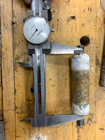
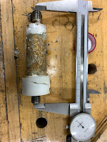
the rudder pivots on a 50mm Aluminum axle (9), and is guided by another 30mm post(10) that forms a stop at either end of its travel. These two aluminim posts are supported in the rudder casing by Ertacetyl bushings.(7,8) (AKA Acetyl, Delrin) A 140mm long 14mm dia stainless rod (11) passes through each aluminum pin. That rod is threaded at each end, M14 X 2mm, and stainless discs (4,5) are threaded on each side, forming a clamp to hold the aluminum pins sandwiched in the rudder housing. A stainless steel nut finishes each side - double-nutting the assembly in place. The rudder is centred and supported in its case by two thick acetyl washers, (6, cracked in the photo below) one on either side of the rudder axle. Not pictured are two acetyl strips that, like washers #6, hold the rudder square in its casing. They can be seen in the pics below.
Disassembling this rather Balkan cocktail of paint, sealants, molluscs, dissimilar metals, crumbling plastic and and oxygen-deprived stainless steel is not for the faint of heart. Pics tell the story. I could not get the aluminum axle #6 out using my small mallet and brass drift, though I did extract the stainless pin. Some use a BFH to do this, but I think I made and used a puller. The parts need to be replaced and spares stowed for future.
Corrosion and galled threads


Parts I was able to clean up.
.JPG)


No comments:
Post a Comment